
Its been a big few weeks, but it good to able to report that the turret is now mostly complete. Some tricky woodworking is yet to be done, rounding the top edges. To do that we will need to roll-up the tent so that we have enough room to use the tools. For now, that can wait, while we look for a suitable weather window. In the meantime, we will begin fitting the cockpit furniture.
In our last blog, we were just about to fit the top skin, but before we could do that, we needed to install the opening for the helm station hatch, and the electrical cables for the saloon and cockpit lighting, as well as the stern navigation light.


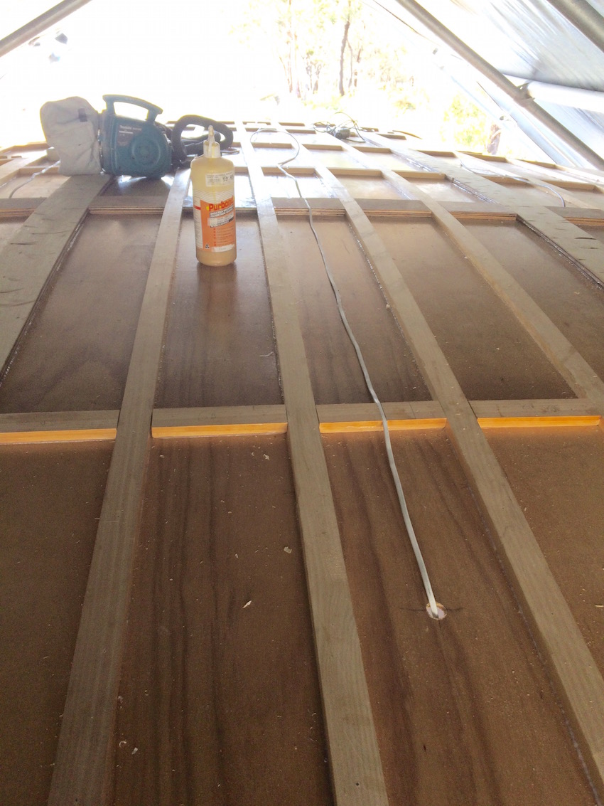
Laying the top sheets of ply was definitely a two person job. These are seriously large lay-ups when using epoxy glue, with its time restrictions. We developed a system that enabled us to lay three sheets in a day. For the interest of the fellow Sarah builders who read this blog, here’s how we did it;
- We drew all the stringer, noggins and but-boards positions onto the top surface of the sheets, making note of the electrical cables.
- We then drilled and pre-loaded the stainless screws onto the sheet. We placed them every 150mm in the flatter areas and 100mm on the tighter curves.
- We mixed two large pots of epoxy, and while Pete resined the underside of the sheet, Deb began laying up the glue mix on the turret. This enabled us to glue the sheets down “wet” for maximum strength.
- After resining the sheet, Pete switched to mixing additional resin for Deb as she worked as quickly as possible to finish laying up.
- We used lots of temporary chipboard screws with washers, around the edges that will later be shaped. Also, we used temporary screws in the areas that will later have hardware fitted, such as genoa tracks and winches.
It was all rather hectic as the weather was warm by Tassy standards, and we had to stay ahead of the resin curing rates.


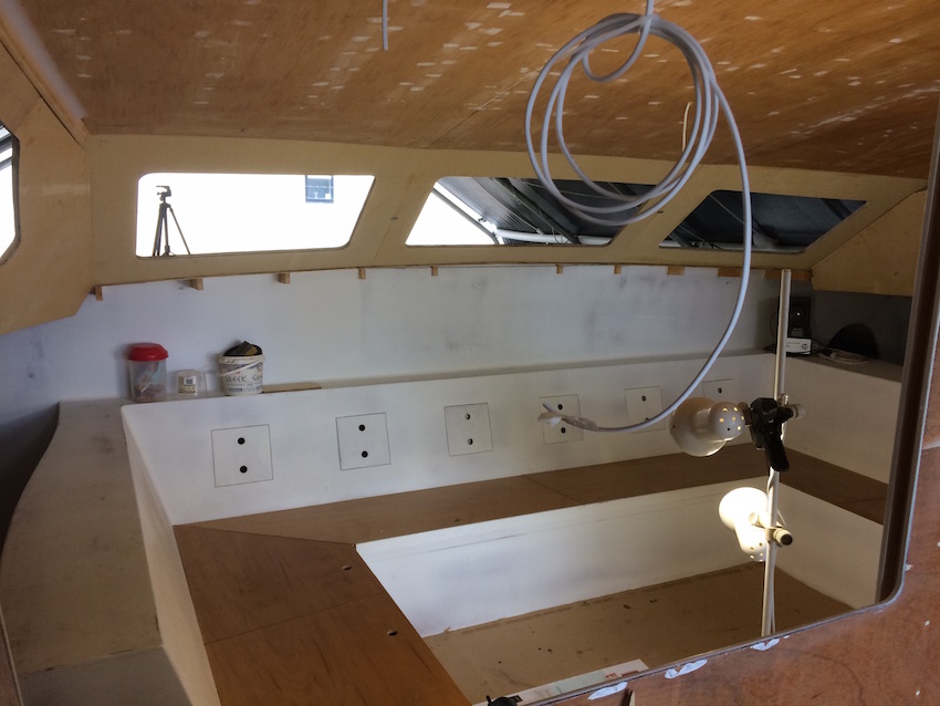
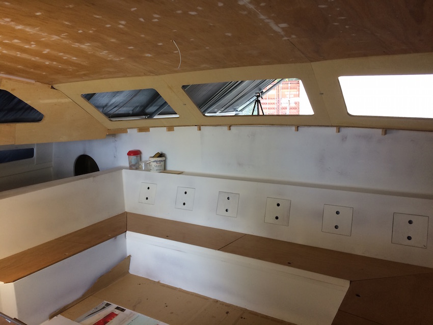
After the top was done, we started work on the forward windows. These windows are an important aspect of Peter Snell’s designs. The two outer windows are fully opening. Combined with the large cockpit windows they provide excellent ventilation for the turret in warmer climes. The side window openings were then cut out. Tricky, because they are done in-situ, not on the bench.

The plans call for the turret sides and front to be re-enforced by double laminating with 9mm ply. This was done after cutting out the side windows, using the cutt-offs. The second skin was laminated slightly oversize, and a trimmer fitted with a bearing guided router bit used to flush up.
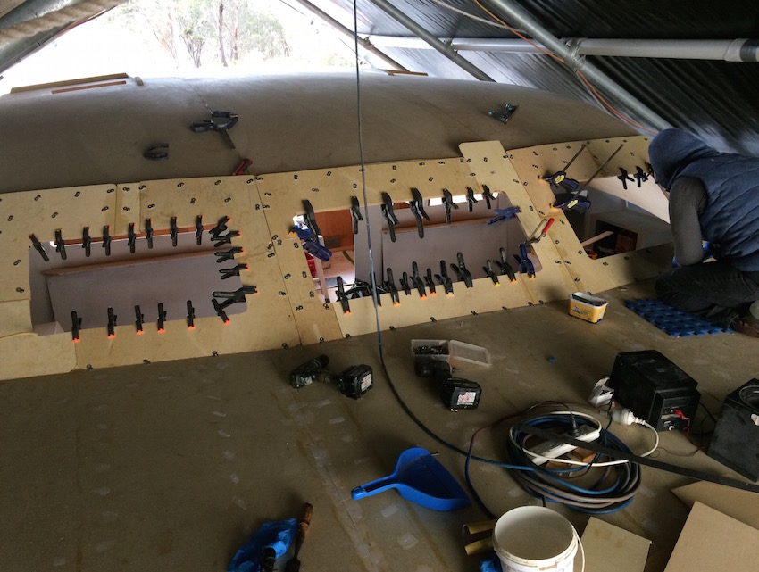
The designer suggested we use the re-enforcement beams to create rain catchment guttering.


I am very impressed every time you post. Thank you for sharing this portion of your life.
LikeLike
Thanks Dean. Appreciate your thoughts. I guess the winter months make it hard to progress your build . Must be frustrating. All the best with it mate.
LikeLike
I am very impressed every time you post. Thank you for sharing this portion of your life.
I am very curious though to see how your cockpit windows will slide up and down. Everything else dust far has been exactly how I have envisioned it. I’m assuming you just like me have done endless hours of research not only with the designer but other designs as well.
Cheers , Dean
LikeLike
Hi Dean. Yes, im wondering about the windows as well, but can only be guided by the other builders. As you are probably aware, there is a standard “C” section auto window trim fitted into the rebate that allows the windows to slide up and down. The rebate has to be cut oversize on the inside, to allow the perspex/ polly carbonate to be inserted. The removable panels then screw over the top to hold it all in place. I’ve seen the windows in action and they seem to work fine. Locating suitable catches that both look good, and don’t “pop” under wind pressure (from astern), seems to be a bit of a thing though. It will be interesting to see what you can find, with the bigger range of hardware options available to you over there. Yep: I’ve spent lots of time on the net, mostly looking for hardware. In general terms though, I’m sticking closely to the design, and the build photos Peter & Anne supplied with the plans. I learned early on, that there is good thinking behind Pete’s methodology.
LikeLike