
So it turns out that this turret of ours is a more complex fabrication than first meets the eye. Hidden between the two outer layers of 6mm plywood, are all manner of structural reinforcements, bearers and butt-blocks. Just about all of it is a critical load-bearing fabrication in one way or another, so every glue lay-up had to be done with care to ensure full glue coverage.
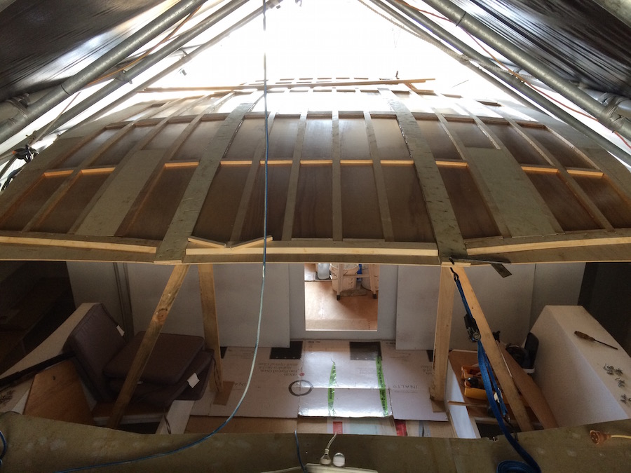
On our last post, we had fitted the bottom sheets, and joined them lengthways with two double layer butt-blocks. The next step was to fix the bearers . These run the full length of the roof.

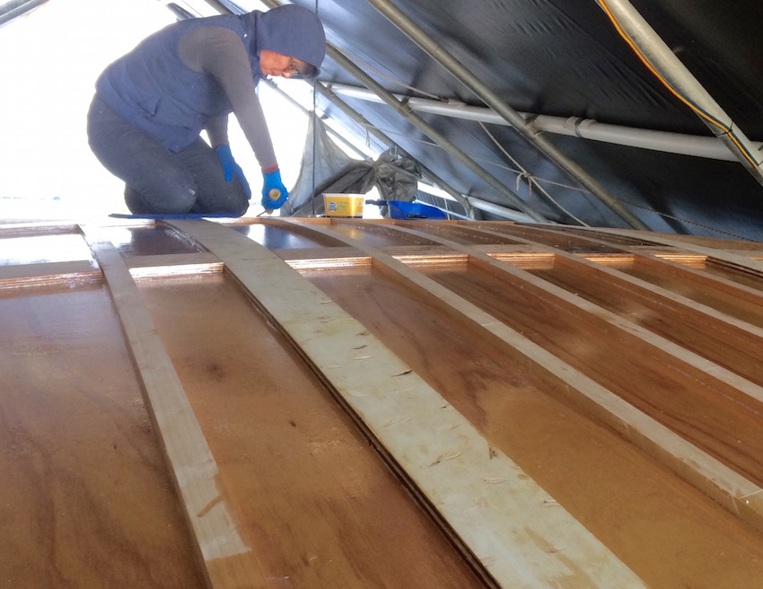
At this point it became apparent to us, just how much epoxy resin this fabrication will soak up. We estimate fabricating the decks and turret will use as much resin as building, fiberglassing and Qcelling an entire hull.
After that, Deb was commissioned to cut out something like 80 butt-blocks, packing pieces and noggins for the athwartships re-enforcement. It gave us an opportunity to use up much of our left over plywood.

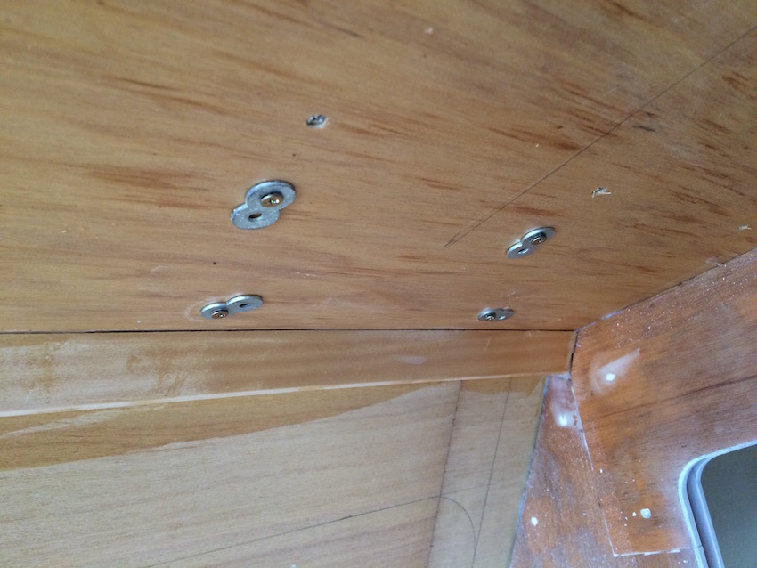
The plans specify that all the butt-blocks, winch packers, mainsheet and genoa traveler packers are fabricated out of two layers of 9mm ply to be glued down onto the 6mm roof-top, then covered with a second skin of ply. The safest way to ensure 100 percent glue contact, in these circumstances is to fix each layer, one at a time. However, given the size of the job, we needed to glue the layers down together. Screwing through three layers can be tricky, as a gap can be left between the layers. To avoid this, it is necessary to drill a slightly oversized hole in the two lower layers, which allows the fastening screw to spin freely. The screw will then grip the top layer (which is not drilled) so that it pulls down to form a tight sandwich. We used cabinetmaker self tapping chipboard screws, with a figure 8 washer to prevent the screw heads burying. Managing all of this, with lengthy glued-up slippery components, required some logistical planning, and a little trial and error, but we soon worked out the best work-flow to get the job done as quickly as possible. The chipboard screws have incredible holding power and we were very happy with how the system worked. We carefully checked every joint for voids, looking for the tell-tale evidence of glue oozing from the layers.


Another big job has been ticked off the to-do list with the final selection and ordering of our electrical components. This is a big deal, as decisions we make now will have a major impact on our quality of life when we move aboard. There is nothing worse than nursing limited batteries, and having to be a power consumption nazi when guests are aboard. Fortunately we have had assistance from Kevin Walker, a retired electrical engineer, who has taken us under his wing, and has been invaluable in ensuring we have chosen the best options for our budget. The heart of our system will be the Victron Easysolar. It combines a solar regulator, inverter and battery charger in a single unit along with a 240volt circuit breaker board. We have ordered two, large Flexipanel solar panels, that will supply a theoretical 540 watts. They are designed for RV’s and boats, and weigh a total of 12 kilos, as opposed to 40 kilos for conventional solid panels. Not the cheapest option, but they are class A rated, meaning they are capable of delivering their advertised wattage in ideal conditions. We have learned that there really is a difference between cheap Ebay panels and the expensive brand name ones, that cost three times as much. Completing the package will be a 400/ah bank of LiFePO4 (Lithium) batteries and a Honda 2KW generator that will be housed in a cockpit locker. Everything plugs into the Easysolar, which seamlessly switches between battery, generator or shore power as necessary.

The Easysolar unit is a mildly controversial choice, as some of our sailing mates are concerned about placing so much trust in a single unit. Time will tell if we have made the right decision. To us, however, this concern is offset by the ease and neatness of the installation. We will be wiring the 12 volt circuits ourselves under Kevin’s guidance. The 240 volt circuits will be installed and certified by a licensed electrician.
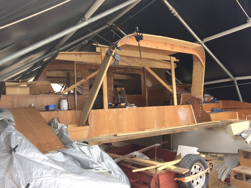
Having taken a day off the build to sort out the electrical installation, we returned to site to complete the fabrication of the targa bar. This entailed laminating nine layers of 4mm ply into the curve scribed by the Oregon cross beam. Great fun, and very satisfying to feel the strength curved lamination creates. To top it off, large radius fillets and no less than four layers of 300gsm cloth re-enforce the assembly. This will ensure it can carry the weight of the dingy.

On a personal note: we are avid watchers of Grand Designs, so it was exciting to tune in last Friday to see the featured home by Pete’s old boss Greg Kay and his partner. There is a connection with Selah. Way back in 1984 Greg took a chance on a 23 year old Pete, gave him a job in his photographic business, with Pete eventually becoming co-manager of his chain of one-hour photo labs (remember them?). Greg was before his time and set up an AMP annuity fund for his managers. Thirty years later, this had grown to become the principal source of funding for building Selah. More importantly however, Greg’s belief in Pete set us up on a life trajectory for which we have always been grateful.
If you are interested you can watch it (for the next month) on iView: https://iview.abc.net.au/show/grand-designs-australia/series/2/video/ZW1452A009S00


Great read yet again Pete and Deb
John L
LikeLike
Thanks John. We can see the light at the end of the tunnel.
LikeLike
As I read now it makes a little more sense having seen it☺..but only a little😆
LikeLiked by 1 person
LOL … same here!
LikeLike